文章目录
- 1 前言
- 2 硬件
- 3 安装库AnalogPin
- 4 读取串口sound数据
- 5 点亮led
- 6 定时中断1s
-
- 6.1 参考文档
- 6.2 增加定时器――安装MsTimer2库
- 6.3 增加定时器――使用hw_timer_t
- 6.4 小结
- 7 结合定时和声音获取
-
- 7.1 代码
- 7.2 结果
- 7.3 分析中断异常
- 7 问题分析――使用hw_timer_t
1 前言
之前用python实现过,参见【掌控板-mpython】3、向txt文件写入字符串、声音数据获取
尝试基于ardiuno抓取并计算采样率
2 硬件

采用的是IO36,对应P10。

3 安装库AnalogPin
查看源码路径:
mind+的arduino:
D:\mind+\Arduino\libraries
arduino的安装lib:
C:\Users\XXXX\Documents\Arduino\libraries
查看mind+中sound信息:D:\mind+\Arduino\libraries\MPython\MPython.cpp
查找到使用的是AnalogPin,io口为A0,这个A0支持自己配置,查看下light对应的正好是IO39,故sound的A0应该为36。
//MPython.cpp
AnalogPin light(39), sound(A0);
查看下AnalogPin的定义
提供了一个read函数,初始化是输入io信息。
analogRead就不展开了,参见文章arduino 的analogRead() 和analogWrite()
模拟输入analogRead()函数的返回值范围是0 到1023;???
//MPython.h
class AnalogPin
{

public:AnalogPin(uint8_t _io);uint16_t read();
private:uint8_t io;
};//MPython.cpp
AnalogPin::AnalogPin(uint8_t _io): io(_io)
{

}uint16_t AnalogPin::read()
{
    return analogRead(io);
}
可以看到返回值类型为uint16_t,即2字节

4 读取串口sound数据
参考代码:Arduino例程解读与实验1.AnalogReadSerial(用串口读取模拟口数据)
/************************func 1 analogRead sound *************************/
# define A_SOUND 36
# define A_LIGHT 39
//sound is IO36
//light is IO39void setup() {
    // initialize serial communication at 9600 bits per second:Serial.begin(9600);
}void loop() {
    // read the input on analog pin 0://读取A0脚输入值大小(0-5V对应0~1023)int sensorValue = analogRead(A_SOUND);// print out the value you read:Serial.println(sensorValue);delay(1); // delay 1 ms in between reads for stability}
5 点亮led
实现定时点亮
/************************func 2 light led *************************/
#include <Arduino.h>
#include <Adafruit_NeoPixel.h>
Adafruit_NeoPixel pixels(3,17, NEO_GRB + NEO_KHZ800);bool status_led = false;void led_on(){
    pixels.setPixelColor(0, pixels.Color(10, 0, 0));pixels.show();Serial.println("led_on");
}void led_off(){
    pixels.setPixelColor(0, pixels.Color(0, 0, 0));pixels.show();Serial.println("led_off");
}void change_led_status(){
    if (status_led == false){
    led_on();status_led = true;}else if (status_led == true){
    led_off();status_led = false;}elseSerial.println("status_led error.");
}void setup() {
    Serial.begin(9600);pixels.begin();// set time}
void loop() {
    // judge time IRQchange_led_status();delay(500);
}
6 定时中断1s
增加定时中断,时间为1s,查看抓取到多少此sound数据
设置一个定时器,每1s点亮或者熄灭led灯。
6.1 参考文档
参考文章:Arduino 定时器中断 外部中断
arduino定时器
6.2 增加定时器――安装MsTimer2库
定时中断有两种,一种是有外接的硬件定时器,当时间到了硬件定时器会发送中断,另一种是软件定时器,根据程序运行时间产生中断。
目前掌控板上未找到硬件定时器。

可以查看下提供的示例。
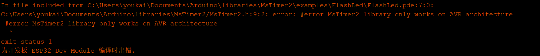
报错只支持AVR
安装avrprog,依旧无效
示例也无效

6.3 增加定时器――使用hw_timer_t
///************************
// func 3 time irq -- hw_timer_t
// error: reboot
//*************************/#include <Arduino.h>
#include <Adafruit_NeoPixel.h>
Adafruit_NeoPixel pixels(3,17, NEO_GRB + NEO_KHZ800);volatile bool status_led = false;void led_on(){
    pixels.setPixelColor(0, pixels.Color(10, 0, 0));pixels.show();Serial.println("led_on");
}void led_off(){
    pixels.setPixelColor(0, pixels.Color(0, 0, 0));pixels.show();Serial.println("led_off");
}void change_led_status(){
    if (status_led == false){
    led_on();status_led = true;}else if (status_led == true){
    led_off();status_led = false;}elseSerial.println("status_led error.");
}hw_timer_t * timer = NULL;            //声明一个定时器//void IRAM_ATTR onTimer() { //中断函数
void IRAM_ATTR onTimer() {
                //中断函数
// change_led_status();Serial.println('2');
}void setup() {
    Serial.begin(115200);                        timer = timerBegin(0, 80, true);                //初始化timerAttachInterrupt(timer, &onTimer, true);    //调用中断函数timerAlarmWrite(timer, 1000000, true);        //timerBegin的参数二 80位80MHZ,这里为1000000 意思为1秒timerAlarmEnable(timer);                //定时器使能//timerDetachInterrupt(timer); //关闭定时器
}void loop() {
    }
若不执行change_led_status()函数,则可以正常运行,但增加该函数,则会不断重启

参考资料:Arduino定时器中断attachInterrupt()详解
6.4 小结
两种方法创建定时器中断均失败,不确定是什么原因导致的,如果有遇到过相同问题的朋友可以一起讨论下,谢谢~
7 结合定时和声音获取
7.1 代码
尝试直接在定时中断中打印log,然后循环中读取sound并计数。
/************************func 4 analogRead sound + time irq *************************/
# include <Arduino.h>
# define A_SOUND 36
# define A_LIGHT 39
//sound is IO36
//light is IO39int count_sound = 0;
volatile int status_time_irq = 0;hw_timer_t * timer = NULL;            //声明一个定时器//void IRAM_ATTR onTimer() { //中断函数
void IRAM_ATTR onTimer() {
                //中断函数
// change_led_status();
// status_time_irq = 1;Serial.println("xxxxxx");
}void setup() {
    // initialize serial communication at 9600 bits per second:Serial.begin(115200);                        timer = timerBegin(0, 80, true);                //初始化timerAttachInterrupt(timer, &onTimer, true);    //调用中断函数timerAlarmWrite(timer, 1000000, true);        //timerBegin的参数二 80位80MHZ,这里为1000000 意思为1秒timerAlarmEnable(timer);                //定时器使能}void loop() {
    if (status_time_irq == 1)
// return;Serial.println("irq");else{
    // read the input on analog pin 0://读取A0脚输入值大小(0-5V对应0~1023)int sensorValue = analogRead(A_SOUND);// print out the value you read:Serial.println(count_sound);
// Serial.print('\t');
// Serial.println(sensorValue);count_sound = count_sound +1;}// delay(1); // delay 1 ms in between reads for stability}
7.2 结果

如图,计数到到2125时,出现异常并重启
关机log为:Guru Meditation Error: Core 1 panic’ed (Interrupt wdt timeout on CPU1)
7.3 分析中断异常
根据提示的log
参考文章:[esp32] Guru Meditation 错误解析及解决方案
ESP32 官方文档(五)严重错误
Interrupt wdt timeout on CPU0 / CPU1(看门狗超时)
表示发生了中断看门狗超时. 有关详细信息,请参阅看门狗.
重点可能要看下watchdog
参考论坛:Interrupt wdt timeout on CPU0
看起来使用双核来避免这个问题,不过现在报错的是cpu1.
7 问题分析――使用hw_timer_t
参考文章:
[ESP32系列教程]ESP32 Arduino教程:定时器中断
[ESP32系列教程]ESP32 MicroPython教程:定时器中断
根据参考文章得到两点
1 为使编译器将代码分配到IRAM内,中断处理程序应该具有 IRAM_ATTR属性。而且,根据IDF文档的说明(参见此处),中断处理程序只能调用同样位于IRAM内的函数。
2